Modelling a Truss Bridge
Geometry & Trigonometry
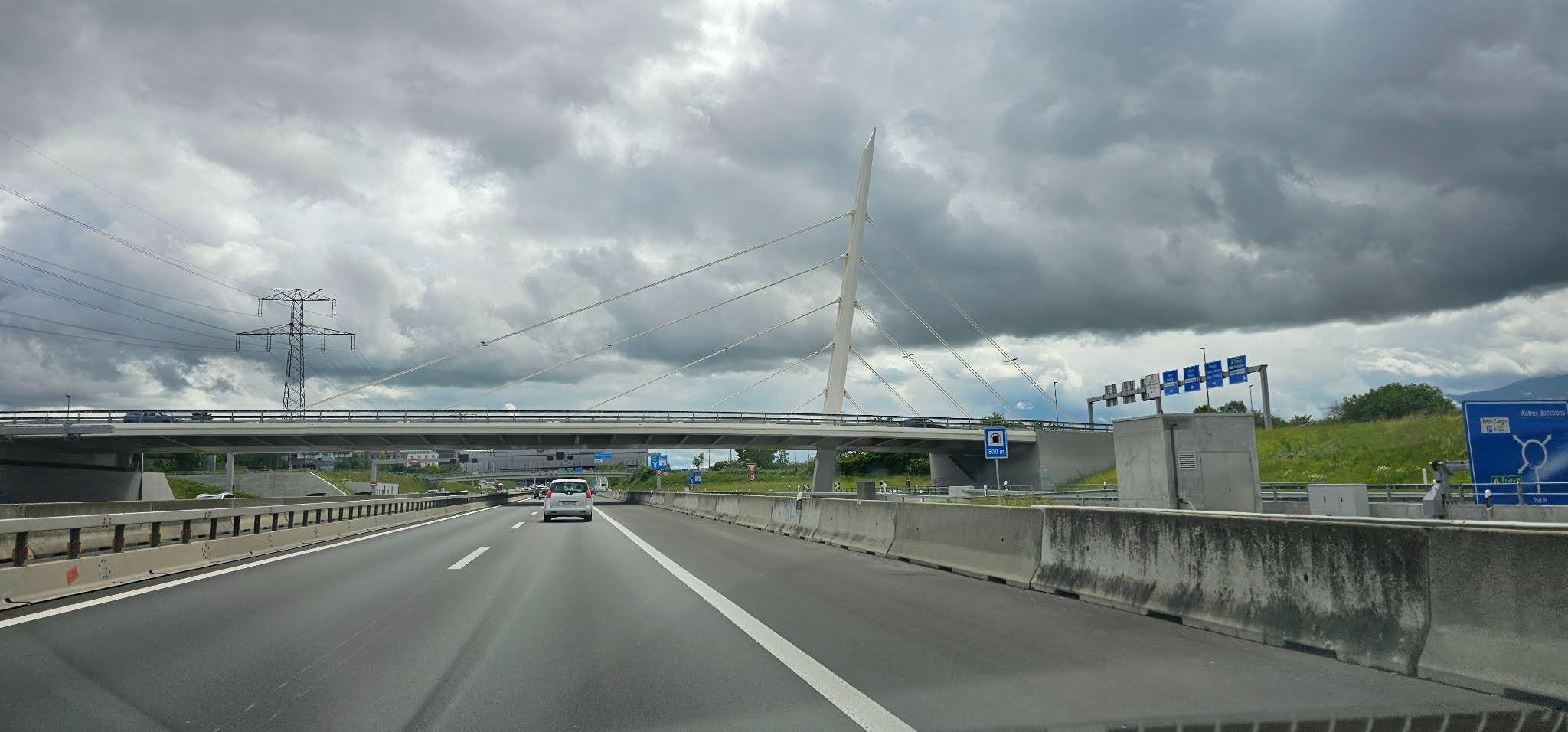
A steel truss bridge carries its load through triangular frames of straight members in tension or compression. Find the forces in each member and the length of cable needed for a chosen span.
Introduction
In a truss bridge, straight steel members meeting at triangular joints carry the load, some in tension (pulling) and some in compression (pushing). This exploration analyses one such bridge: resolving the forces at each joint to find which members pull and which push, calculating the tension needed in supporting cables for a realistic load, and working out the total length of cable or steel required for a chosen span and angle.
Guiding Questions
- Which parts of this bridge push and which pull? Sketch the forces at a few key joints.
- Resolve the forces at one joint into components and find the tensions for realistic loads.
- How does the force in each member change as a load moves across the bridge?
- Build or simulate a small version. Do the measurements match your calculations?